
BOSA and Its Production Process
2024-01-26
The most important and core thing in optical communication is the optical module. In the historical development of optical communication, the main thing is the innovation of the performance indicators of the optical transceiver module. The most basic function of the optical transceiver is to complete the optical-to-electrical or electro-to-optical conversion function of the optical signal, in other words, to complete the photoelectric conversion. Its interior mainly comprises optical devices, functional circuits, and optical interfaces.
Among them, optical devices are the main components of optical transceiver modules. One is TOSA (Transmitting Optical Sub-Assembly, light emitting component), and the other is ROSA (Receiving Optical Sub-Assembly, light receiving component).
The optical devices used in early optical modules were separate for receiving and transmitting. With the development of miniaturization, the two were combined into one to form BOSA (Bi-Directional Optical Sub-Assembly, light transmitting and receiving assembly).
What is BOSA?
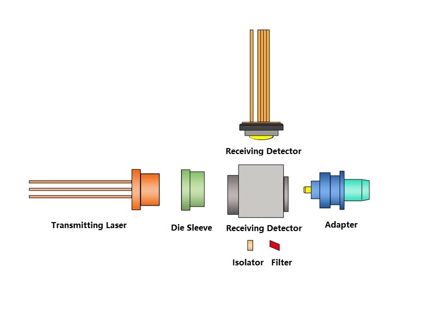
Bi-Directional Optical Sub-Assembly (BOSA) refers to a single-fiber bidirectional optical device, which mainly consists of a transmitting laser, a receiving detector, an adapter, a filter, a base, an isolator and a die sleeve. Or TOSA and ROSA can be integrated into the transceiver of the light source (LD and PIN/APD) through the coaxial coupling process, plus components composed of splitters, optical fibers, etc. The main function is to convert electrical signals and optical signals into each other.
BOSA Key Components
BOSA mainly contains the following key components:
BOSA Production Process
The main production process of BOSA is: marking - installing beam splitter - assembling LD - LD assembly surface inspection and spot welding - transmitting coupling - welding - receiving coupling - glue sealing - transmitting and receiving parameter detection.
1. Marking: A laser is used to print an“ID card”on the outside of the metal structure of the component, and its parameters are entered into the system to facilitate tracking and inspection.
2. Install the beam splitter: The role of the beam splitter is to separate the light received and emitted in the optical fiber. The LD is press-fitted into a metal structural part with a beam splitter mounted on it.
3. LD assembly surface inspection and spot welding: The assembled metal structural parts with LD are inspected under a microscope to check the press-fitting effect to see if there are any undesirable conditions such as pin tilt. After checking that there are no problems, the LD and structural parts will be laser spot welded to fix the LD.
4. Emission coupling and welding: By adjusting the relative position of the SC connector structural part and the LD, the light emitted by the LD is coupled into the optical fiber of the SC connector part as much as possible. After the adjustment is completed, the structural parts of the SC joint part and the structural parts with the LD pressed are fixed by laser spot welding.
5. Receiving coupling and sealing: It is to adjust the relative position of the PD and the structural parts equipped with LD so that more optical signals from the optical fiber are coupled to the PD to improve the receiving sensitivity of the PD. After the adjustment reaches the index requirements, the PD and structural parts are glued and sealed to fix the PD.


