
A Complete Guide to Fiber Array Units: The Critical Interface Between Optical Fibers and Chips
2026-09-30
As 800G and 1.6T optical modules, Co-Packaged Optics (CPO), Near-Packaged Optics (NPO), and AI data centers continue to evolve, optical interconnects are moving from traditional board-level and module-level connections toward chip-level optical interconnects. In this transition, the Fiber Array Unit (FAU) plays a critical role despite its compact size. It precisely aligns and connects multiple optical fibers with Photonic Integrated Circuits (PICs) or Optical Engines (OEs), enabling stable, low-loss optical coupling. In simple terms, an FAU serves as a critical optical interface between the fiber world and the chip world.
1. What Is an FAU?
1.1 Basic Structure of an FAU
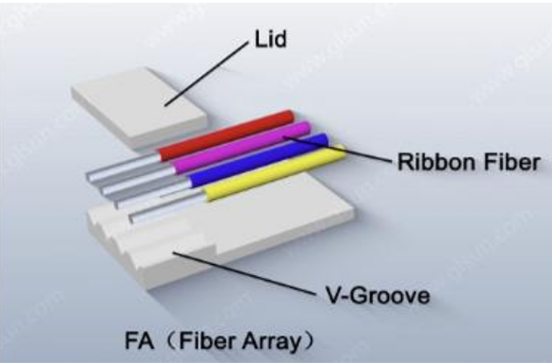
A Fiber Array Unit (FAU) is an optical assembly that precisely positions, aligns, and permanently fixes multiple optical fibers at a predefined pitch and arrangement. Its core functions can be summarized as:
Precise fiber alignment → Accurate optical positioning → Stable chip coupling → Long-term optical stability
A typical FAU consists of several key components:
· V-Groove: Provides precision positioning for optical fibers
· Ribbon Fiber / Bare Fiber: Enables multi-channel parallel optical transmission
· Lid: Holds the fibers in position during permanent fixation
· Optical Adhesive: Provides long-term mechanical fixation
· Substrate: Provides mechanical support for the fiber array
The structure can be understood simply as:
· V-Groove = Foundation, providing precise positioning
· Fiber = Optical channel, carrying signals
· Lid + Adhesive = Fixation, maintaining long-term stability
It is also important to distinguish between the terms FA (Fiber Array) and FAU (Fiber Array Unit). An FA generally refers to the fiber array itself, while an FAU typically refers to the complete fiber-array assembly after precision alignment, fixation, and packaging.
2. How Is an FAU Related to PICs and Optical Engines?
An FAU does not perform optical-to-electrical conversion itself. Its primary function is to provide optical alignment and coupling between fibers and the chip-side optical interface. In a high-speed optical interconnect system, the signal path can be simplified as: Fiber → FAU → PIC / Optical Engine → Electrical Interface → Chiplet / HBM
Where:
· Fiber: Transmits optical signals over distance
· FAU: Precisely arranges and connects multiple fibers to the chip-side optical interface
· PIC (Photonic Integrated Circuit): Performs photonic functions such as modulation, splitting, multiplexing, and demultiplexing
· OE (Optical Engine): Integrates optical components with the required electrical interfaces
· Chiplet: A modular processing die
· HBM: High Bandwidth Memory
· Package Substrate: Provides high-speed electrical interconnection
In AI computing systems, optical engines work together with computing dies, HBM, and other components to form high-performance computing platforms. Therefore, an FAU can be viewed as: A precision optical interface connecting external fibers to chip-level optical interfaces.
3. The Core Technology of FAUs: Precision Optical Coupling
Why Is FAU Packaging Important?
When an FAU is connected to a PIC, the fiber array must be precisely aligned with the optical coupling region on the chip. For high-speed optical interconnects, even a small positional deviation can significantly affect coupling efficiency and optical loss. Therefore, FAU packaging is far more than simply fixing fibers in place. It involves multiple precision processes, including:
· Fiber-array positioning
· Optical-axis alignment
· Mode-field matching
· Active or passive alignment
· Adhesive curing
· Thermal-stress control
· Long-term reliability verification
The ultimate objective is to achieve:
Low insertion loss + High coupling efficiency + High reliability + High yield + Scalable manufacturing
These requirements are also among the key technical barriers as FAUs evolve from conventional fiber arrays toward advanced optical interfaces for CPO.
4. Edge Coupling vs. Grating Coupling
Based on the coupling architecture between the fiber array and PIC, FAU-related solutions can generally be categorized into Edge Coupling and Grating Coupling.
4.1 Edge Coupling
In an edge-coupling configuration, the fiber end faces in the FAU are directly aligned with the waveguide facets at the edge of the PIC. The optical signal travels horizontally from the fiber into the chip waveguide. Key advantages include:
· Direct optical path
· High coupling efficiency
· Low insertion loss
· Broad optical bandwidth
· Suitability for high-speed, high-bandwidth applications
As a result, edge coupling is an important approach for high-speed optical communications and certain CPO architectures.
4.2 Grating Coupling
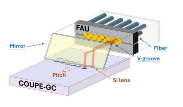
Grating coupling uses a grating structure on the surface of the PIC to achieve vertical optical coupling between the fiber and the chip. In some FAU architectures, the horizontal optical path from the fiber is redirected through: Mirror → Lens → Grating Coupler
A reflector changes the direction of the optical path, while a microlens focuses the beam before it enters the grating coupler on the PIC surface.
Key advantages include:
· Vertical fiber-to-chip coupling
· Compatibility with two-dimensional fiber-array configurations
· Convenient wafer-level optical testing
· Potential for high-density optical I/O architectures
Therefore, vertical coupling offers significant potential for high-density and two-dimensional optical interfaces.
5. How Does a Typical FAU Optical Path Work?
For a vertical-coupling architecture, the optical path can be simplified as:
Fiber → FAU → Mirror → Si Lens → Grating Coupler → PIC
5.1 Fiber: Optical Signal Input
Multiple optical fibers are precisely arranged within the FAU according to the designed channel pitch and optical layout.
5.2 V-Groove: Precision Positioning
The V-Groove mechanically constrains the fiber position, ensuring stable pitch and height across multiple channels.
5.3 Mirror: Optical Path Redirection
When the optical signal exits the fiber horizontally, a reflector with an angle of approximately 45° can redirect the beam, changing the optical path from horizontal to vertical.
5.4 Si Lens: Beam Focusing
Microlens arrays can collimate or focus the optical beam so that the beam size better matches the optical mode of the chip, thereby reducing coupling loss.
5.5 Grating Coupler: Optical Entry into the PIC
The optical signal is finally coupled into the PIC through the grating coupler and enters the on-chip waveguide. This architecture illustrates the real value of an FAU:
An FAU is not simply a mechanism for arranging fibers. It is a precision optical interface designed around positioning, beam routing, focusing, and optical coupling.
6. What Are the Main Components of an FAU?
A complete FAU generally consists of several key components.
6.1 V-Groove Substrate
The V-Groove substrate is one of the most important mechanical structures of an FAU. Common substrate materials include:
· Fused silica / quartz glass
· Silicon
· Ceramic
Precision machining is used to create V-shaped grooves that control the position, pitch, and height of each fiber.
6.2 Bare Fiber
During FAU assembly, the fiber coating is stripped in the designated area so that the exposed fiber can be positioned inside the V-Groove. Depending on the application, the fiber may include:
· Single-mode fiber
· Multimode fiber
· Polarization-maintaining (PM) fiber
· Customized specialty fibers
6.3 Lid and Adhesive
After the fibers are precisely positioned, a lid and optical adhesive are used to secure the fiber array. For high-end FAUs, the adhesive must be carefully selected based on:
· Shrinkage
· Curing temperature
· Coefficient of thermal expansion
· Long-term reliability
· Moisture resistance
· Optical stability
These factors directly affect the long-term stability of optical alignment.
7. Where Are the Key Manufacturing Challenges?
Although the structure of an FAU may appear relatively simple, its manufacturing process requires extremely high precision and consistency. One of the most critical steps is: Fiber Placement into the V-Groove
Multiple bare fibers must be accurately positioned and seated into the V-Grooves according to the specified pitch and orientation. For conventional FAUs, manufacturers need to control:
· Fiber pitch
· Fiber height
· End-face position
· Fiber-axis parallelism
For Polarization-Maintaining FAUs (PM-FAUs), the manufacturing challenge becomes even greater.
In addition to positional accuracy, the polarization-axis orientation of each PM fiber must also be controlled.Precision assembly may therefore require microscopic or machine-vision-based positioning and angular adjustment. This leads to an important conclusion: The technical barriers of FAUs lie not only in materials and structural design, but also in precision assembly, active alignment, adhesive curing, process control, and scalable manufacturing.
8. Major Types of FAUs
As optical communications and photonic integration continue to evolve, FAUs are moving toward higher channel counts, higher density, polarization-maintaining designs, and greater reliability.
8.1 MT-FA
MT-FA is a common multi-fiber array solution used in conventional optical communications. Typical configurations include:
8-fiber, 12-fiber, and 24-fiber arrays
As high-speed optical modules and high-density optical interconnects continue to develop, higher-channel-count configurations are also emerging. Typical applications include:
· High-speed optical modules
· Optical communication equipment
· Data centers
· Optical interconnect assemblies
8.2 PM-FAU: Polarization-Maintaining Fiber Array Unit
PM-FAUs use polarization-maintaining fibers to preserve the polarization state of optical signals.One of the key performance indicators is the Polarization Extinction Ratio (PER). Typical applications include:
· Coherent optical communications
· High-performance optical modules
· Fiber-optic sensing
· Laser systems
· Selected CPO and photonic integration applications
Compared with conventional FAUs, PM-FAUs require tighter control of fiber orientation, assembly accuracy, and long-term stability.
8.3 FAUs for CPO
CPO brings optical engines closer to the computing chip, placing greater demands on FAU packaging. Typical requirements include:
· High-temperature reliability
· High channel density
· Compact form factor
· Low optical loss
· High mechanical stability
· High-density fiber arrangement
As optical I/O moves closer to the chip, FAUs are evolving from conventional module-level connection components into chip-level optical interfaces.
8.4 High-Density Matrix FAUs
In addition to conventional optical modules, FAUs can also be used in high-density optical switching and optical interconnect systems. Potential applications include:
· OCS (Optical Circuit Switching)
· Optical switching systems
· Optical matrices
· High-density optical interconnects
These applications require greater control over: Channel count, spatial layout, insertion-loss uniformity, fiber positioning accuracy, and system-level integration.
9. Why Are FAUs Becoming More Important in the AI Era?
The growth of FAUs is being driven not only by higher optical-module speeds, but also by fundamental changes in AI computing architectures.
9.1 AI Is Driving Higher Optical I/O Requirements
AI training and inference clusters require massive amounts of data exchange among GPUs, CPUs, accelerators, and HBM. As computing scale increases, electrical interconnects face growing challenges in terms of:
· Bandwidth
· Power consumption
· Transmission distance
· Signal integrity
Optical interconnects are therefore moving progressively closer to the computing chip. This means: More optical fibers → More optical I/O → More FAUs → Higher FAU channel density
9.2 CPO and NPO Are Increasing the Value of FAUs
In traditional pluggable optical modules, the optical engine is physically separated from the switching ASIC. In CPO architectures, the optical engine moves much closer to the switching chip and can be integrated within the same package. This can shorten high-speed electrical interconnects and provide a new pathway toward higher bandwidth and lower-power optical connectivity. At the same time, the optical fiber interface must also move closer to the chip. Therefore, the closer the optical engine moves to the chip, the more important the FAU becomes. The FAU is no longer simply responsible for arranging fibers; it becomes part of the precision optical I/O interface in chip-level optical packaging.
10. From 1D Arrays to 2D and Higher-Density Architectures
Traditional FAUs are primarily based on one-dimensional fiber arrangements. For next-generation CPO, NPO, and high-density optical I/O packaging, fiber arrays are evolving toward: 1D Arrays → 2D Arrays → Higher-Density Spatial Arrays
At the same time, coupling architectures are also evolving from conventional edge coupling toward vertical coupling and more sophisticated multi-dimensional optical designs. This evolution will drive continuous improvements in:
· Miniaturization
· Fiber density
· Alignment precision
· Integration
· Automated manufacturing
11. The Market Value of FAUs Is Changing
From a supply-chain perspective, FAUs have traditionally been regarded as supporting optical components within optical modules.However, with the development of 800G, 1.6T and higher-speed optical modules, as well as CPO and NPO architectures, the value proposition of FAUs is changing. Three major trends are particularly important.
11.1 Higher Channel Counts
Fiber arrays are evolving from 8/12/24 channels toward higher channel counts, increasing the number of optical I/O channels supported by a single FAU.
11.2 Increasing Product Complexity
FAUs are no longer simply fiber-positioning components. Advanced designs can integrate: Fiber Array + Microlens + Reflector + Optical Coupling Structure + Precision Packaging. This increases both manufacturing complexity and product value.
11.3 From Module-Level to Chip-Level
In conventional optical modules, FAUs primarily address optical fiber connections within the module. In CPO and NPO architectures, FAUs can directly participate in chip-level optical I/O connections. As a result, FAUs are gradually evolving from: “Optical module supporting components” into: “Critical interfaces for high-speed optical interconnects.”
It is important to note that market-size estimates for FAUs vary significantly depending on the definition and scope used by different research organizations. Some reports include related connectors, microlenses, or optical packaging components, while others focus only on the FAU itself. Therefore, market figures should always be evaluated together with their source, market definition, geographic scope, and forecast period.
12. Key Technology Trends for Future FAUs
Driven by AI computing, CPO, NPO, and next-generation optical modules, future FAUs are expected to evolve in several key directions.
① Higher Density
More fibers, tighter pitch, and higher optical I/O density.
② Lower Optical Loss
Optimization of fibers, lenses, reflectors, and coupling structures to further reduce optical loss.
③ Higher Alignment Precision
Moving toward increasingly stringent sub-micron optical alignment requirements.
④ Higher Reliability
Improved stability under high-temperature, humidity, mechanical stress, and long-term operating conditions.
⑤ Higher Automation
Machine vision, automated fiber placement, active alignment, and automated curing will help improve manufacturing efficiency and consistency.
⑥ Higher Integration
FAUs are evolving from simple fiber arrays toward highly integrated optical interfaces combining:
Fiber + Lens + Mirror + Coupler + PIC
13. Conclusion
FAUs Are Becoming a Critical Interface Between Light and Chips
Structurally, an FAU may appear relatively simple. However, as optical interconnects evolve from conventional optical modules toward CPO, NPO, and chip-level optical I/O, the role of the FAU is changing significantly. An FAU is no longer simply responsible for: “Arranging optical fibers.”
It must also:
“Precisely align the optical path, minimize optical loss, maintain mechanical stability, and ensure long-term reliability under demanding packaging conditions.”
As a result, FAUs are becoming increasingly important components in the high-speed optical interconnect ecosystem. From conventional optical modules to 800G/1.6T optical interconnects, and further toward CPO, NPO, and AI computing systems, fiber arrays are evolving from conventional connection components into critical chip-level optical I/O interfaces.
Going forward, as AI computing continues to scale and photonic integration advances, FAUs will continue to evolve toward:
Higher Density · Lower Loss · Higher Precision · Higher Reliability · Higher Integration
Ultimately, the FAU is becoming one of the key building blocks connecting optical fibers, photonic chips, and the next generation of AI computing infrastructure.