
Basic Principle of Optical Fiber Transmission
2023-02-09
The signal undergoes total reflection in the optical fiber to complete end-to-end transmission after the optical signal enters the optical fiber through the optical interface.
Optical signal transmission in optical fiber will be affected by the characteristics of optical fiber, including optical power loss, dispersion and nonlinearity, etc.
![]()
Loss
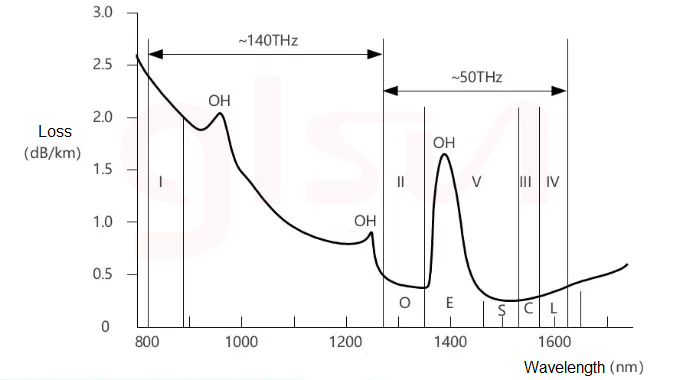
The loss is the decrease of the optical power when it is transmitted in the optical fiber, indicating the transmission loss of optical signal energy by the optical fiber, and is an important basis for evaluating the quality of optical fiber and determining the relay distance of optical fiber communication system. It is generally expressed in dB/km.
Causes of Loss: light absorption loss, light signal scattering and additional loss.
Absorption loss refers to the loss of optical power caused by the conversion of part of light energy into heat energy when light waves pass through optical fiber materials. Including intrinsic absorption and impurity absorption.
Intrinsic Absorption: The inherent absorption of optical fiber base materials (such as SiO2) is not caused by impurities or defects. Therefore, the intrinsic absorption basically determines the lower limit of absorption loss of a certain material.
Impurity Absorption: additional absorption loss caused by the impurity of the fiber material (dust, metal ions, etc.)
Scattering: When light passes through inhomogeneous materials such as density or refractive index, light can also be seen in other directions besides the propagation direction of light. This phenomenon is called light scattering.
Scattering loss: the loss caused by the scattering of the light conducted in the optical fiber due to the defects or non-uniformity of the material, shape, and refractive index distribution of the optical fiber.
Additional loss: due to the optical fiber being bunched into optical fiber cable, the additional loss is caused by the optical fiber laying, optical fiber connection and coupling and connection as a system in various environments.
Bending loss and microbending loss of optical fiber/cable.
Connection loss in fiber optic lines.
Coupling loss between optical devices.
For example, single-mode fiber has three low-loss windows, namely 850nm, 1310nm and 1550nm. The latter two windows are commonly used. The attenuation of the 1310nm window is 0.3~0.4dB/km; the attenuation of the 1550nm window is 0.19~0.25dB/km , and the engineering value is 0.275dB/km.
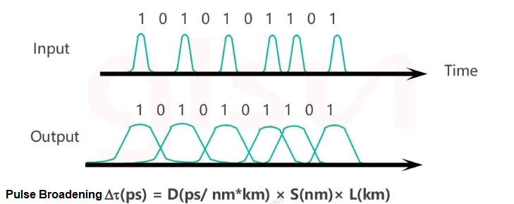
Dispersion
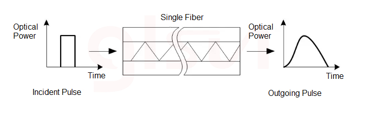
Dispersion: When the incident optical pulse signal at the input end of optical fiber is transmitted over a long distance, at the output end of the optical fiber, the optical pulse waveform is broadened in time, resulting in inter-symbol interference at the output end of the optical fiber. This phenomenon is called dispersion.
Dispersion Representation: Differential Group Delay
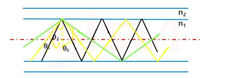
Mode Dispersion: the delay difference caused by different modes of optical signals. As shown in the figure, the propagation speed of rays ① and ② along the axis direction is different. The difference between the fastest and slowest modes is described by the maximum delay difference.
Chromatic Dispersion: including structural dispersion and material dispersion. The transmission speed of different spectral components in optical pulse signal is different in optical fiber, resulting in the pulse signal broadening and even dispersion after transmission. The gap may not be very large when the distance is short, and the gap will be widened as the distance is long.
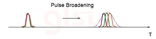
The influence of chromatic dispersion: lead to signal pulse broadening, resulting in signal transmission errors.
From the perspective of the system, the fiber dispersion is proportional to the length of the fiber, that is, the fiber dispersion is cumulative, so there is a transmission distance limit determined by the fiber dispersion in the design of the optical communication system.
For ultra-long distance or long distance, it is necessary to use dispersion compensating fiber (DCF) with negative wavelength dispersion to compensate the dispersion and reduce the total dispersion of the entire transmission line.
Polarization Mode Dispersion PMD: The transmission of light in an optical fiber can be described as vibrations entirely along the X-axis and entirely along the Y-axis or some light vibrates in both axes.
The core ellipticity and stress caused by environmental factors and process defects can almost be ignored, but can not be completely eliminated, and can only be minimized from optical devices. In ultra-high-speed systems with narrower pulse width, the greater the impact of PMD.


