
Function and Basic Principle of Optical Isolator
2023-07-22
An optical isolator is an optical component that allows the transmission of light in only one direction. It is typically used to prevent unwanted feedback into an optical oscillator, such as a laser cavity.
The function of the optical isolator is to let the light transmitted in the forward direction pass through and isolate the light transmitted in the reverse direction, so as to prevent the reflected light from affecting the stability of the system, similar to the function of a diode in an electronic device. Optical isolators are divided into two types according to polarization dependence: polarization-dependent type and polarization-independent type. The former is also called free space type (Free Space ) because there is no optical fiber input and output at both ends; the latter is also called in-line type ( In -Line) because there are optical fiber input and output at both ends. Free-space optical isolators are generally used in semiconductor lasers, because the light emitted by semiconductor lasers has extremely high linearity, so this polarization-dependent optical isolator can be used to enjoy the advantage of low cost; in communication lines or EDFAs, in-line optical isolators are generally used, because the optical polarization characteristics on the line are very unstable, requiring devices to have small polarization-dependent losses.
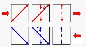
The basic principle used by the optical isolator is Malus’ law of polarized light and Faraday’s magneto-optical effect. The basic structure and principle of the free-space optical isolator are shown in the figure below. It consists of a magnetic ring, a Faraday optical rotator and two polarizers. Forward incident linearly polarized light, whose polarization direction is along the transmission axis direction of polarizer 1, rotates 45° counterclockwise to the transmission axis direction of polarizer 2 when passing through the Faraday rotator, and transmits smoothly; reversely incident linearly polarized light, whose polarization direction is along the transmission axis direction of polarizer 2, still rotates 45° counterclockwise to be perpendicular to the transmission axis of polarizer 1 when passing through the Faraday rotator, and is isolated without transmission light. The free-space optical isolator is relatively simple. When assembling, the polarizer and the optical rotator are tilted at a certain angle (such as 4°) to reduce the reflected light on the surface. Pay attention to the repeatability of the test when building the test structure.
The earliest online optical isolator was made of a combination of Displacer crystal and Faraday rotator, which was replaced by Wedge optical isolator due to its large size and high cost; online optical isolator introduced PMD due to the use of birefringent crystal, so PMD compensation type Wedge isolator appeared accordingly; some applications put forward higher requirements for isolation, so dual-stage optical isolators appeared to obtain higher isolation in a wider bandwidth.
The structure and principle of inline optical isolator.
1) Displacer type optical isolator
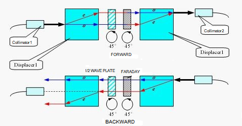
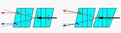
The structure and optical path of the displacer type optical isolator are shown in the figure below. It consists of two collimators, two Displacer crystals, a half-wave plate, a Faraday optical plate and a magnetic ring (not shown in the figure). The forward light is incident on the Displacer from the collimator 1 On 1, it is divided into o-light and e-light transmission, after passing through the half-wave plate and Faraday rotation plate, it rotates 45 +45 =90 counterclockwise, the conversion of o-light and e-light occurs, and passes through the Displacer 2 synthesize a beam and couple it into collimator 2; the reverse light is incident on Displacer2 from collimator 2, and is divided into o light and e light for transmission. After passing through the Faraday rotation plate and half-wave plate, it rotates counterclockwise by 45 -45 =0, no conversion of o light and e light occurs, and passes through Dis placer 1 The latter two beams are separated by deviation from the collimator 1.
The disadvantage of the Displacer-type optical isolator is that in order to meet the isolation requirements, the two beams of light in the reverse optical path need to be offset by a large distance, as shown in Figure 2(a), and the ratio of the length to the offset of the yttrium vanadate Displacer crystal with better birefringence characteristics can only be 10:1, which requires the Displacer crystal to be very large, resulting in large device volume and high cost.
2) Wedge type optical isolator
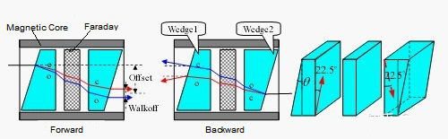
The structure and optical path of the Wedge optical isolator are shown in the figure below. It consists of two collimators (not shown in the figure), a magnetic ring, a Faraday rotator and two wedge-shaped birefringent crystals. The optical axes of the two wedges form an angle of 45°. The forward light from the input collimator is Wedge 1 Divided into o-light and e-light and transmitted separately, when passing through the optical rotator, the polarization direction is rotated 45° counterclockwise (observed against the direction of forward light propagation, the same below), and enters the Wedge At 2, no conversion of o light and e light occurs, so the polarization states of the two beams of light in the two wedge angles are o→o and e→e respectively. The combination of two wedge angle plates is equivalent to a parallel plate for the forward light. 2 Divided into o light and e light and transmitted separately, the polarization direction is still rotated 45° counterclockwise when passing through the optical rotator, and enters the W edge When 1, the conversion of o light and e light occurs, so the polarization states of the two beams in the two angle wedges are o→e and e→o. The combination of the two angle wedges is equivalent to a Wollaston prism for the reverse light. After the reverse light passes, it deviates from the original direction and cannot be coupled into the input collimator.
Note that after the forward light is divided into two beams and passes through, the lateral displacement Offset occurs relative to the incident light, and the two beams are separated by a certain distance Walkoff. The refractive index of the two beams in the angle wedge is different, so PMD is introduced. Offset should be considered in package design; Walkoff is generally about 10um, which will introduce a little PDL, but it has little relationship; for PMD, it can be compensated as needed. The PMD compensation method is to add a birefringent crystal plate at the back, and its optical axis is the same as Wedge The optical axis of 2 is vertical, and the thickness is calculated by optical path tracing, which will not be repeated here.
Compared with the Displacer type optical isolator, the Wedge type optical isolator has a very different isolation mechanism for the reverse light. The former makes the reverse light move laterally relative to the input collimator, and the latter makes the reverse light deviate relative to the input collimator. It can be seen from Figure 2 (a) and (c) that the isolation effect of the latter is better. The cross-sectional area of the Wedge crystal only needs to ensure the effective aperture for the passing light spot, and the thickness only needs to be easy to assemble. Therefore, the crystal volume of the Wedge type optical isolator is small, so the device is small in size and low in cost, and has replaced the Displacer type.
3) Two-stage optical isolator
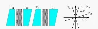
Two-stage optical isolator scheme 1, two single-stage optical isolator cores are connected in series, and the optical axis direction of each wedge is also shown in the figure. The forward light is o light and e light in the first and second stages respectively, so the PMD generated by the two stages compensates each other. The disadvantage of this scheme is that the assembly accuracy is very high, otherwise the isolation index is worse than that of a single-stage optical isolator.
Two-stage optical isolator scheme two, two single-stage optical isolators are connected in series with relative rotation of 45°. The disadvantage of this scheme is that it is difficult to adjust the isolation and PMD to the best state at the same time during rotation. Therefore, the two stages are firstly compensated for PMD, and then rotated relative to each other. This can make a qualified two-stage optical isolator, but the yield rate and efficiency are still low due to the complexity of the process.
The only difference between the two-stage optical isolator scheme 3 and the scheme 1 is that the angles of the front and rear two-stage wedges are different. Next, we will analyze the scheme 1 to understand the changes of the scheme 3.
First of all, let's understand why the dual-stage optical isolator can obtain higher isolation than the single-stage optical isolator. As mentioned earlier, the Wedge-type optical isolator makes the reverse light deviate from the collimator by an angle to achieve the purpose of isolation. For the yttrium vanadate wedge with an angle of 5° and the lithium niobate wedge with a 13° angle, the reverse light is deflected at an angle of about 1°. As can be seen from Figure 2(e), considering this angle alone, the isolation of a single-stage optical isolator can far exceed 60dB. The reason that really restricts its isolation is the extinction ratio and wavelength dependence of the Faraday rotator. The former is about 40-50dB, and the latter is about -0.068°/nm. Therefore, the peak isolation of a single-stage optical isolator is about 40-50dB, and the isolation within a 30nm bandwidth is >30dB. The double-stage optical isolator makes the reverse light deflect at a larger angle, but it is the icing on the cake. What really works is that the two-stage series connection overcomes the constraints of the extinction ratio and wavelength dependence of the optical rotator.
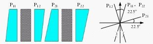
Scheme 1, the reverse light starts to be divided into two paths in P22, and the polarization states in each angle wedge are o→e→o→e and e→o→e→o, which is equivalent to passing through two Wollaston prisms, so the deviation angle is about twice that of a single-stage optical isolator. The above assumes that the optical axes of the corner wedges are in the ideal direction. Now we assume that the optical axes of the corner wedges P12 and P21 are not completely perpendicular, and the angle between them is 90°-Δ. Then the two paths of light entering P12 from P21 will be divided into two paths of propagation. Therefore, in addition to the above two paths of polarization, the polarization states of the other two paths of light are o→e→e→o and e→o→o→e, and the intensity of the two beams of light is sin (Δ). Considering the polarization states of the latter two paths of light, the combination of P12 and P21 is equivalent to a parallel plate, and the combination of P11 and P22 is equivalent to another parallel plate. Therefore, the direction of the two paths of light does not change after passing through, or it can be explained that the front and rear stages are equivalent to two inverted Wollaston prisms. The beam deviated by the second stage is returned by the first stage, as shown in Figure 24. These two paths of light are directly coupled into the collimator at the input end, which becomes the main reason for restricting the isolation. Taking Δ=0.1° and 0.2° respectively, the isolation is 55dB and 49dB, which shows that the assembly accuracy is very high. Scheme 3 uses different angles for the angle wedges in the two stages, and the beam deflected by the second stage will not be completely returned by the first stage, because the deflection angle is approximately proportional to the size of the wedge angle.
The core of solution three is to understand that the non-perpendicularity of the optical axes of P12 and P21 is very important to the isolation. A solution is proposed. Using the corresponding assembly process, a dual-stage optical isolator with high isolation can be produced, and the efficiency can be improved due to the large assembly tolerance.


